
The input board is a small PCB mounted directly on the connector.
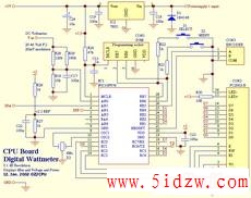
The main CPU board is mounted directly on the display.
Updated 3. Sep. 2002.
If you are from Denmark ! read the Danish version !!
In the good old days I had some parts but now
This Wattmeter is in ELEKTOR MAGAZINE OKTOBER 2002, they will sell PIC and PCB
The extra input B is for a later SWR brigde project, also the TX serial output will be in use later.
The uncalibrated signal response is: +1/-1 dB from 1MHz to 450MHz.
Input SWR vill varry from 1.00 to 1.30, depending on input Frequency.
To make the SWR this good, you need to assemble the input circuit correct and adjust the capasitor.
Input power range: -60 to +30dBm that is 1 nW to 1 Watt.
This instrument CAN be used and calibrated from 1 kHz and up to 500 MHz
It is possible to measure power relative all the way up to 900Mhz
A SOFtware routine can calibrate the 0dBm point at 5 different frequencies to make this instrument aCCurate within 0.5dBm !!
The calibration data is stored in EEPROM so the instrument will remember all, also without power.
At frequencies above 300Mhz this instrument should not exceed inputs over +20dBm (100mW) to keep the good accuacy
This is a documented weekness in the AD8307, this is not a big problem, if you are aware of this, then it's just a matter of using the right input attenuator
If battery opperation: do not connect R30, also change R26 and R27 to 4k7
Ideas taken from articles in: QST June 2001 page 38 and Funkamateur 12/99 page 1383 And Elektor 1/99 page 26

The display, shows dBm from -60 to +30dBm, RF Voltage and RF Power and Bargraph in 1db step.
The backlite is verry powerfull, I had to change R30 to 10E
Also I must complement the POWERTIP display for it's exelent contrast and viewing angle and low prize !
I use a POWERTIP display with 20 caracters in 2 lines with LED light.
Powersupply current is:
With no light: = 30 mA. (R30 = NC)
Normal light: = 120 mA. (R30 = 10E)
Power light: = 200 mA. (R30 = 4E7)
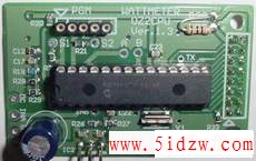
Here is main PCB assembled, ready to be mounted on the display.
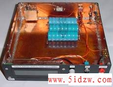
The cabinet is homemade of glasfiber PCB, easy and cheap to construct.
There is made plenty of room for a batteryPACk, and also I like it not to be too small
so that it's hard to come in and make modifications.
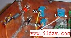
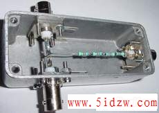
Here a view of the back side of the switches and the rotary encoder
note the RF filter on the DC voltage input.
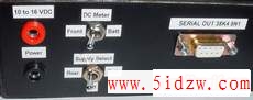
The backside powersupply input, and powersupply selector switch
The DC voltmeter switch is connected so that it's only possible to measure the battery voltage when it's running on battery.
Here is how I have connected the two switches, the charge resistor and diode needs to be adjusted to fit the used battery.
If no battery supply is needed, only one switch is then mounted.
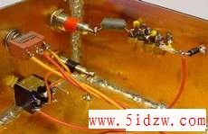
Also the powersupply cords can transfer unwanted RF noice, so here is also added a RF bLOCking filter
Note the diode and little-fuse for reverse polarity protection.
The NEW version of the PCB Now the input coil has been removed
The AD8307 is SMD SO-8, the extra input board is for a later project (SWR bridge), more about this next year.
The TX serial out PIN is for several future projects, that uses a PC to draw curves and more.
The bottom PCB side is mostly shilding PCB size is 79mm wide and 37mm height
Here is all the measurements curves
Software information users guide and download
PC logger software for windows
Complete part list
Assembly and solder instructions
Digital Wattmeter construction-competition
Serial output format and hardware sorry this page only in Danish
Front plate and box design Here is my sugestion about how to do it
Comments, Ideas, News from all of us to all of you
Output to freq counter and DFD4 counter modifications
F6GOG Wattmeter page A must see page !!
How To Measure High Power
The digital-powermeter input range is 1nW to 1W.To measure more power an attenuator can be mounted in front of it, but they are expensive !
A good and cheap solution is to use a -40 dB tab.
The Wattmeter readout can be set to show correct values, using five standard attenuators,
Attenuator settings: none, -10, -20, -30, -40 and -50dB, by this it is now possible to measure from 1nW up to 100 kW
Here is my simple homemade -40dB tap, using 3 BNC connectors a small cheap box and a few resistors.