The four first resistors is 620 Ohm each the bottom resistors is two 100 Ohm in parallel.
This uncompensated circuit can be used up to 170 Mhz and up to 50 Watts continius
This is a much better solution, but also a bit harder to make
This -40dB tab has good SWR up to 900 MHz, and the -40dB output signal has a perfect flat response up to 600Mhz
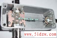
The 2.7mm stripline needs to be verry acurate, the PCB is double sided 1.6mm thick.
note that the stripline goes all the way as close as possible to the connector isolation
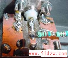
Here is a closeup, note the tab compensation wire, that is adjusted close to the two first resistors,
by this way it is possible to adjust a perfect flat -40 dB response up to 600 MHz
This tab can also only handle 50 Watts, limited by the four 1/4 watt resistors
To get -40dB a 100:1 voltage divider is made with 50 Ohm output impedance, so when this output is loaded
the total load resistance is 25 Ohm, now that we have the output bottom resistance of 25 Ohm we can calculate
the total resistance of the 100:1 voltage divider, 100 * 25 = 2500 Ohm so the top resistance is 2500 - 25 = 2475 Ohm
if four resistors is used they shuld be 2475 / 4 = 618.75 Ohm so I use 620 Ohm that is a standard
Power in the resistors: I use 250 mW resistors * 4 = 1 Watt the power in the bottom resistors is negible..
To calgulate the MAX RF power level, U = square root P * R, it was 1W and 2500 Ohm this give 50 Volt, this is equal to 50 W
the resistors can stand the double power for about 1 minute and 4 times a few sec, so to my needs this is fine
a 30dB attenuator
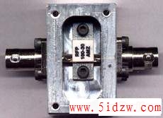
Ready made attenuator modules is made by several companies. Here is a 30 dB 100Watt from RF Power
Their web site www.rf-power.com
In this case it can not with stand 100 Watt so long, due to the lack of heat sink
The 30 dB attenuation is verry acurate from 0 to 500 Mhz, it has also perfect return loss
I know a nice person that have access to a CNC machine, he made this alu box for me.[---分页---]
Front Plate and case creation

The front plate, width = 204 mm Hight = 54 mm
I have made this front plate design with my PCB program
Then it is easy to make the rest few plates and solder them to a box.
After that, paint it black or what ever collor you like.
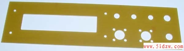
Here is the front plate PCB just arrived from the PCB manufacture
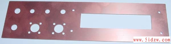
The rear side is COBber, so that it is easy to solder the walls to it.
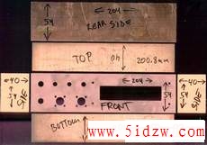
Here is all the PCB parts before soldering.
The depth of 40 mm is the minimum size, now there is no room for batteries or RS-232
All measurements in millimeters as usual.
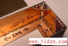
Here is the M3 nut, before it is soldered to the mounting plate.
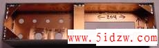
Case is now almost ready for painting.
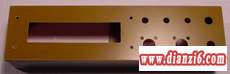
Seen from front, just before painting.
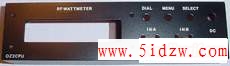
When it is painted, the text can be added, use SENO or LETRA-SET,
Then a transparent paint is sprayed on to secure the text.
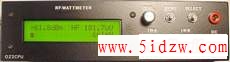
Here the unit finished !