��ǩ���������칦��,���칦�ŵ�·,http://www.5idzw.com
Reference Design for a Class-D, 2.1 Channel, Audio Amplifier for an MP3 Player Docking Station,http://www.5idzw.com
Abstract: This reference design demonstrates the use of the MAX9736 Class D audio amplifier in a stereo audio, docking station application. The MAX9736 2.1 demo box is a complete powered speaker dock that uses two MAX9736 ICs to drive a 3-channel speaker system consisting of two 2in satellite speakers and one 5in subwoofer. The reference design is intended to be used with a portable audio player as its main music source. The overall solution size is very compact and features active equalization, power-supply monitoring, and dynamic equalization for the subwoofer.
Important Design Features
Bill of Materials Designator Qty Description C1 1 470µF ��20% 25V aluminum electrolytic capacitor
Panasonic® EEU-FM1E471 C2, C12, C310 3 0.1µF ��10% 50V X7R ceramic capacitor (0603)
Murata® GRM188R71H104K
TDK C1608X7R1H104K C321 1 1µF (0603) C16 1 10µF (1206) C106, C109�C111, C114, C206, C209�C211, C214 10 NS (0603) C3�C5 3 0.1µF ��10% 16V X7R ceramic capacitor (0603)
Murata GRM188R71C104K
TDK C1608X7R1C104K C13 1 0.1µF (0603) C316�C317 2 0.1µF (0805) C303 1 0.33µF (0603) C302 1 0.47µF (0603) C305, C307 2 100nF (0603) C103�C104, C203�C204, C301 5 100pF (0603) C121, C220�C221, C120, C314�C315 6 100pF (0603) C117�C119, C217�C219 6 10nF (0603) C107, C207 2 150pF (0603) C306, C308 2 15nF (0603) C6�C10, C15, C313, C318�C320 10 1µF ��10% 16V X7R ceramic capacitor (0603)
Murata GRM188R71C105K
TDK C1608X7R1C105K C312, C14, C311 3 1µF (0603) C216, C116 2 1µF (0805) C100�C101, C200�C201 4 2.2µF (0805) C304 1 2.2µF (0805) C102, C108, C112, C115, C202, C215, C300 7 33pF (0603) C208, C212 2 33pF (0603) C322 1 33pF (0603) C113, C213 2 4.7nF (0603) C105, C205 2 68nF (0603) C11, C309 2 220µF ��20% 35V aluminum electrolytic capacitor (10mm x 12.5mm)
Panasonic EEUFM1V221 J30 1 4-pin header
HIROSE DF3A-4P U7 1 Opto-FET (DIP6-SMT)
Fairchild™ H11F1SM L100�C101, L200�C201, L300�C301 6 Ferrite bead (1206) FB1 1 Ferrite bead (1206) J3 1 6-pin header J10, J20 2 2-pin header
HIROSE DF3A-2P J2 1 RCA® dual jack PCB mount D1 1 LED red (0603) D5 1 LED blue (0603) Q2 1 Transistor NPN (SOT23)
Fairchild MMBT3904 X1�C2 2 Connector, screw mount R7 1 Potentiometer 100K SMT R303 1 Potentiometer 20K SMT J1 1 Power jack, right angle
Switchcraft® 722RA R1 1 10k�� ��5% resistor (0805) R110, R210 2 NS resistor (0603) R111, R211 2 10.5k�� ��5% resistor (0603) R100, R200 2 100�� ��5% resistor (0603) R10 1 100k�� ��1% resistor (0603) R106, R108, R206, R208 4 10k�� ��5% resistor (0603) R300�C301 2 10k�� ��5% resistor (0603) R2�C3 2 10k�� ��1% resistor (0603) R113, R213 2 11k�� ��5% resistor (0603) R309, R311�C312, R314 4 11k�� ��5% resistor (0603) R306 1 12k�� ��5% resistor (0603) R114, R214 2 137k�� ��5% resistor (0603) R305 1 14.7k�� ��5% resistor (0603) R112, R212 2 150�� ��5% resistor (0603) R317 1 1k�� ��5% resistor (0603) R107, R109, R207, R209 4 1M�� ��5% resistor (0603) R8�C9, R315�C316 4 2.2k�� ��5% resistor (0603) R101�C102, R201�C202 4 20k�� ��5% resistor (0603) R5 1 220�� ��5% resistor (0603) R310, R313 2 24.3k�� ��5% resistor (0603) R302 1 2k�� ��5% resistor (0603) R308 1 3.24k�� ��5% resistor (0603) R307 1 3.3k�� ��5% resistor (0603) R115, R215 2 30.1k�� ��5% resistor (0603) R4 1 4.22k�� ��1% resistor (0603) R103�C104, R203�C204 4 40k�� ��5% resistor (0603) R304 1 7.15k�� ��5% resistor (0603) R105, R205 2 0�� resistor (0603) D6 1 Diode, dual, common-cathode (SOT-23-3)
Fairchild MMBD4148CC D2�C3 2 Zener diode 4.3V, 20mA (SOT-23)
Central CMPZ5229B SPK1, SPK2 2 2in full-range loudspeaker
Tymphany® 830970 SPK3 1 5.25in subwoofer loudspeaker
Tymphany 830945 U1 1 Maxim® MAX9736BETJ+
(7mm x 7mm, 32-pin TQFN) U2 1 Maxim MAX9736AETJ+
(7mm x 7mm, 32-pin TQFN) U3�C5 3 Maxim MAX4234 (TSSOP-14) U6 1 Maxim MAX809_EUR-T (SOT-23)
The design features two 2in loudspeaker drivers for the left and right channels, and a 5in loudspeaker for the subwoofer. A single MAX9736B is used in stereo mode for the left/right channels and a MAX9736A is used in mono mode for the subwoofer channel. The detailed description here is divided into two sections: electronic circuit description and speakers/physical enclosure description.
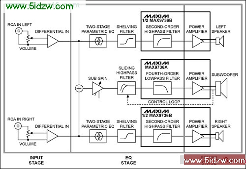
Figure 1. Electrical circuit block diagram features the MAX9736 Class D audio amplifier. The design has an input, EQ, and power stage.
��Reference Design for a Class-D, 2.1 Channel, Audio Amplifier for an MP3 Player Docking Station
Abstract: This reference design demonstrates the use of the MAX9736 Class D audio amplifier in a stereo audio, docking station application. The MAX9736 2.1 demo box is a complete powered speaker dock that uses two MAX9736 ICs to drive a 3-channel speaker system consisting of two 2in satellite speakers and one 5in subwoofer. The reference design is intended to be used with a portable audio player as its main music source. The overall solution size is very compact and features active equalization, power-supply monitoring, and dynamic equalization for the subwoofer.
Important Design Features
- Compact all-in-one design
- Operates from a single 12V to 20V DC power supply
- High SPL output from a small box
- High-efficiency Class-D design
- Active EQ, including dynamic bass equalization
- Excellent sound quality from cost-effective drivers
Bill of Materials Designator Qty Description C1 1 470µF ��20% 25V aluminum electrolytic capacitor
Panasonic® EEU-FM1E471 C2, C12, C310 3 0.1µF ��10% 50V X7R ceramic capacitor (0603)
Murata® GRM188R71H104K
TDK C1608X7R1H104K C321 1 1µF (0603) C16 1 10µF (1206) C106, C109�C111, C114, C206, C209�C211, C214 10 NS (0603) C3�C5 3 0.1µF ��10% 16V X7R ceramic capacitor (0603)
Murata GRM188R71C104K
TDK C1608X7R1C104K C13 1 0.1µF (0603) C316�C317 2 0.1µF (0805) C303 1 0.33µF (0603) C302 1 0.47µF (0603) C305, C307 2 100nF (0603) C103�C104, C203�C204, C301 5 100pF (0603) C121, C220�C221, C120, C314�C315 6 100pF (0603) C117�C119, C217�C219 6 10nF (0603) C107, C207 2 150pF (0603) C306, C308 2 15nF (0603) C6�C10, C15, C313, C318�C320 10 1µF ��10% 16V X7R ceramic capacitor (0603)
Murata GRM188R71C105K
TDK C1608X7R1C105K C312, C14, C311 3 1µF (0603) C216, C116 2 1µF (0805) C100�C101, C200�C201 4 2.2µF (0805) C304 1 2.2µF (0805) C102, C108, C112, C115, C202, C215, C300 7 33pF (0603) C208, C212 2 33pF (0603) C322 1 33pF (0603) C113, C213 2 4.7nF (0603) C105, C205 2 68nF (0603) C11, C309 2 220µF ��20% 35V aluminum electrolytic capacitor (10mm x 12.5mm)
Panasonic EEUFM1V221 J30 1 4-pin header
HIROSE DF3A-4P U7 1 Opto-FET (DIP6-SMT)
Fairchild™ H11F1SM L100�C101, L200�C201, L300�C301 6 Ferrite bead (1206) FB1 1 Ferrite bead (1206) J3 1 6-pin header J10, J20 2 2-pin header
HIROSE DF3A-2P J2 1 RCA® dual jack PCB mount D1 1 LED red (0603) D5 1 LED blue (0603) Q2 1 Transistor NPN (SOT23)
Fairchild MMBT3904 X1�C2 2 Connector, screw mount R7 1 Potentiometer 100K SMT R303 1 Potentiometer 20K SMT J1 1 Power jack, right angle
Switchcraft® 722RA R1 1 10k�� ��5% resistor (0805) R110, R210 2 NS resistor (0603) R111, R211 2 10.5k�� ��5% resistor (0603) R100, R200 2 100�� ��5% resistor (0603) R10 1 100k�� ��1% resistor (0603) R106, R108, R206, R208 4 10k�� ��5% resistor (0603) R300�C301 2 10k�� ��5% resistor (0603) R2�C3 2 10k�� ��1% resistor (0603) R113, R213 2 11k�� ��5% resistor (0603) R309, R311�C312, R314 4 11k�� ��5% resistor (0603) R306 1 12k�� ��5% resistor (0603) R114, R214 2 137k�� ��5% resistor (0603) R305 1 14.7k�� ��5% resistor (0603) R112, R212 2 150�� ��5% resistor (0603) R317 1 1k�� ��5% resistor (0603) R107, R109, R207, R209 4 1M�� ��5% resistor (0603) R8�C9, R315�C316 4 2.2k�� ��5% resistor (0603) R101�C102, R201�C202 4 20k�� ��5% resistor (0603) R5 1 220�� ��5% resistor (0603) R310, R313 2 24.3k�� ��5% resistor (0603) R302 1 2k�� ��5% resistor (0603) R308 1 3.24k�� ��5% resistor (0603) R307 1 3.3k�� ��5% resistor (0603) R115, R215 2 30.1k�� ��5% resistor (0603) R4 1 4.22k�� ��1% resistor (0603) R103�C104, R203�C204 4 40k�� ��5% resistor (0603) R304 1 7.15k�� ��5% resistor (0603) R105, R205 2 0�� resistor (0603) D6 1 Diode, dual, common-cathode (SOT-23-3)
Fairchild MMBD4148CC D2�C3 2 Zener diode 4.3V, 20mA (SOT-23)
Central CMPZ5229B SPK1, SPK2 2 2in full-range loudspeaker
Tymphany® 830970 SPK3 1 5.25in subwoofer loudspeaker
Tymphany 830945 U1 1 Maxim® MAX9736BETJ+
(7mm x 7mm, 32-pin TQFN) U2 1 Maxim MAX9736AETJ+
(7mm x 7mm, 32-pin TQFN) U3�C5 3 Maxim MAX4234 (TSSOP-14) U6 1 Maxim MAX809_EUR-T (SOT-23)
Detailed Design Description
The reference design consists of a single, carefully tuned box enclosure containing all of the electronics and speaker hardware. Only an external power supply and a signal source are required to complete the system.The design features two 2in loudspeaker drivers for the left and right channels, and a 5in loudspeaker for the subwoofer. A single MAX9736B is used in stereo mode for the left/right channels and a MAX9736A is used in mono mode for the subwoofer channel. The detailed description here is divided into two sections: electronic circuit description and speakers/physical enclosure description.
Electronic Circuit Description
The electronics of the reference design comprise two sections, the left/right and subwoofer. Each section has three stages: input, EQ, and power. See Figure 1.Figure 1. Electrical circuit block diagram features the MAX9736 Class D audio amplifier. The design has an input, EQ, and power stage.
Input Stage
The input stage is common to both the left/right and subwoofer sections. A stereo, log-taper potentiometer is used as a volume control to adjust the signal level to the preamplifier. To avoid ground loops, the input is sensed differentially and the RCA input connectors are not directly connected to the system ground. A 100�� resistor is used to reduce the common-mode voltage; U3-A and U3-D (see schematics below) perform differential-to-single-ended conversion with a gain of 2. The outputs of the input stage are referred to VREF, the reference voltage of power amplifier U2 which is buffered using U5-D.EQ Stage
After the input stage, the left and right signals are passed to a two-stage parametric EQ built around U3-B (for left) and U3-C (for right). Each parametric EQ uses an op-amp gyrator to simulate an inductor in an LC-series resonant circuit. The series circuit has two access points for either attenuation or boost, and the access points are realized by two different capacitors. C105 and C106, for example, are the boost and attenuation points for the first parametric EQ band for the left channel. If only C106 is used (and C105 is not stuffed), the resonant circuit forms a voltage-divider in combination with the series resistor R105 (10k��), and the resonant frequency is attenuated. Conversely, if only C105 is used, the feedback is reduced, resulting in a boost at the resonant frequency. If neither of the capacitors is used, then the band is disabled.��Reference Design for a Class-D, 2.1 Channel, Audio Amplifier for an MP3 Player Docking Station