标签:汽车音响功放,音响功放电路,http://www.5idzw.com
改善立体声性能与Active偏置-Improve Stereo Performance with Active Biasing,http://www.5idzw.com
Abstract: This application note discusses trade-offs of active and passive biasing circuits used in consumer audio products. The use of these circuits in digital potentiometers and volume controls is compared in terms of audio parameters like separation and mute. Equations help designers evaluate their design trade-offs for a specific situation.

In this application note we will compare active and passive biasing circuits for digital potentiometers. Device performance considerations are reviewed. The article also provides the equations necessary for the designer to make the right trade-offs in consumer products.
The wiper buffer reduces the current through the array of switches to improve their distortion performance. This article explores how the bias generator affects the circuit's performance.
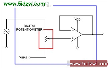
Figure 1. Volume control fed by a signal source.
A digital potentiometer (outlined in red) is an array of switches and resistors controlled by logic that emulates a mechanical potentiometer's sliding contact wiper. A volume-control IC (outlined in blue) is differentiated from the digital potentiometer by the incorporation of two circuits that are very important for best audio performance: the wiper buffer (op amp) and the bias generator (source of VBIAS).
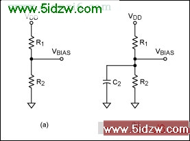
Figure 2. Passive bias circuit.
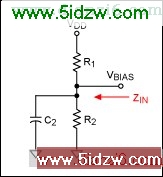
Figure 3. Stiffness is related to the impedance looking into the bias network.
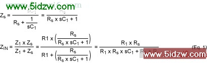
As a check, note that at DC (s = 0), the equation reduces to the impedance of the resistors R1 and R2 in parallel. Now we can insert this impedance into the volume-control circuit (Figure 4).
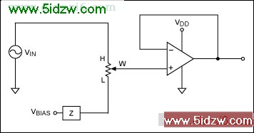
Figure 4. Volume control with finite impedance bias network.
The finite source impedance of the bias network will allow a signal to appear on the L terminal of the digital potentiometer. Setting the wiper to L is supposed to be muted! Instead of seeing no signal, as desired, we will see a divided-down version of the source voltage, VIN.
For example, with the wiper at the L position, a 40kΩ potentiometer, and two 10kΩ bias resistors, we will see an output voltage of:

This is only -19dB below full scale (dBFS) at DC. This means that even if the potentiometer is set to mute, you will still see an output signal.
What happens if we include C2 in the analysis? Let us try a 0.01µF capacitor. The results of Equation 1 are shown in Figure 5.
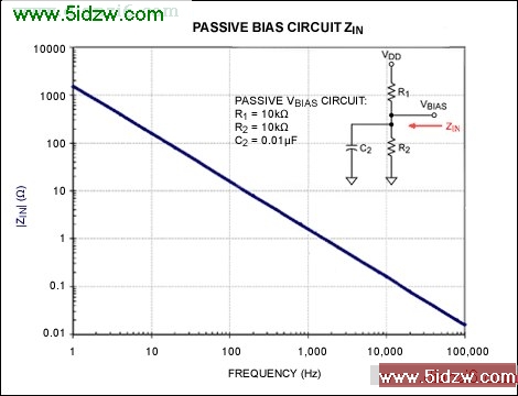
Figure 5. Passive bias network with a 0.01µF capacitor.
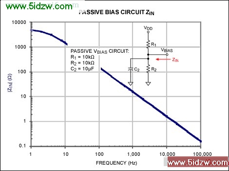
Adding C2 had almost no effect below 1kHz, and the effect at 20kHz only reduces the impedance to 785Ω. We will achieve a mute attenuation of just -34dB, as shown in Figure 5. The capacitor can be raised to 10µF (large) to improve the circuit. At 100Hz we now have a mute attenuation of just -48dB. See Figure 6. This is not even close to the ultimate performance of the volume control, and it is not even close to a reasonable audio specification for mute.
 ,改善立体声性能与Active偏置-Improve Stereo Performance with Active Biasing
Abstract: This application note discusses trade-offs of active and passive biasing circuits used in consumer audio products. The use of these circuits in digital potentiometers and volume controls is compared in terms of audio parameters like separation and mute. Equations help designers evaluate their design trade-offs for a specific situation.
Introduction
Designers of consumer products are pushed to reduce cost at every turn. Although the use of digital potentiometer and volume-control ICs instead of mechanical potentiometers enables a wider variety of user interfaces for your customer, these new ICs require careful attention to circuit details if the best audio performance is to be achieved. Sometimes this means trading off performance parameters and cost.In this application note we will compare active and passive biasing circuits for digital potentiometers. Device performance considerations are reviewed. The article also provides the equations necessary for the designer to make the right trade-offs in consumer products.
Volume Controls and Digital Potentiometers
The circuit below illustrates some of the terminology used in this article. We will be focusing on a single-supply application, which is the most common situation in battery- or wall-adapter-powered products. In a single-supply application all parts of the system are powered with VDD and ground, and signals swing between VDD and ground. Capacitors may be used between stages or they can be eliminated for cost and performance reasons.The wiper buffer reduces the current through the array of switches to improve their distortion performance. This article explores how the bias generator affects the circuit's performance.
Figure 1. Volume control fed by a signal source.
A digital potentiometer (outlined in red) is an array of switches and resistors controlled by logic that emulates a mechanical potentiometer's sliding contact wiper. A volume-control IC (outlined in blue) is differentiated from the digital potentiometer by the incorporation of two circuits that are very important for best audio performance: the wiper buffer (op amp) and the bias generator (source of VBIAS).
Passive Bias Circuit
If you are using a digital potentiometer and trying to keep cost under control, you can generate the bias voltage with a passive resistive divider as shown in Figure 2. The resistor values are typically equal in value to set VBIAS at the midpoint of VDD and ground. To reduce the AC impedance at VBIAS and clean up any noise, most designers will also add a bypass capacitor, C2.Figure 2. Passive bias circuit.
Mono Volume-Control Circuit
Let us take a look at how the chosen circuit values will affect audio performance. The source impedance of the bias circuit, sometimes called the "stiffness" of the supply, is calculated from Figure 3.Figure 3. Stiffness is related to the impedance looking into the bias network.
As a check, note that at DC (s = 0), the equation reduces to the impedance of the resistors R1 and R2 in parallel. Now we can insert this impedance into the volume-control circuit (Figure 4).
Figure 4. Volume control with finite impedance bias network.
The finite source impedance of the bias network will allow a signal to appear on the L terminal of the digital potentiometer. Setting the wiper to L is supposed to be muted! Instead of seeing no signal, as desired, we will see a divided-down version of the source voltage, VIN.
For example, with the wiper at the L position, a 40kΩ potentiometer, and two 10kΩ bias resistors, we will see an output voltage of:
This is only -19dB below full scale (dBFS) at DC. This means that even if the potentiometer is set to mute, you will still see an output signal.
What happens if we include C2 in the analysis? Let us try a 0.01µF capacitor. The results of Equation 1 are shown in Figure 5.
Figure 5. Passive bias network with a 0.01µF capacitor.
Adding C2 had almost no effect below 1kHz, and the effect at 20kHz only reduces the impedance to 785Ω. We will achieve a mute attenuation of just -34dB, as shown in Figure 5. The capacitor can be raised to 10µF (large) to improve the circuit. At 100Hz we now have a mute attenuation of just -48dB. See Figure 6. This is not even close to the ultimate performance of the volume control, and it is not even close to a reasonable audio specification for mute.
,改善立体声性能与Active偏置-Improve Stereo Performance with Active Biasing