标签:汽车音响功放,音响功放电路,http://www.5idzw.com
Reference Design for a Class-D, 2.1 Channel, Audio Amplifier for an MP3 Player Docking Station,http://www.5idzw.com
The resonant frequency, f0, can be calculated using the equation:
As a stereo Class D IC, the MAX9736 also features two integrated op amps at the input. Available to use for general filtering, in this reference design those op amps are used to build a second-order highpass filter for the left/right channels. The op amps have their negative inputs and outputs accessible, so a multiple-feedback inverting filter configuration is used. C116/C216 are for blocking the DC-input voltage to reduce output offset.
In mono mode, the two Class D outputs of the MAX9736A are connected in parallel to allow for higher output power. In mono mode the subwoofer channel can deliver 30W into 4Ω (VDD = 19V). The input stage for the subwoofer channel is the same as that used for the left and right channels. After the input stage, the left and right signals are then summed using U5-B to create the mono subwoofer channel. R303 is used to set the subwoofer channel gain at the summing amp.
To enable a maximally flat response down to very low frequencies, the system is configured with a sixth-order filtered alignment for the subwoofer. This approach means that the fourth-order highpass response of the vented speaker is supplemented with a second-order electrical highpass in the active circuitry. U5-C is used to realize the noninverting Sallen-Key, second-order highpass filter for the subwoofer.
This system requires a high Q, which leads to 13dB of boost at 40Hz. To avoid overloading the speaker and amplifier, the Sallen-Key filter is set up to act as a sliding highpass; the filter acts dynamically as the amplifier output reaches its limit. The value of input resistor R305 is designed to reduce automatically (using the opto-coupled FET, U7) to a value so that the filter Q is lowered to 0.5, resulting in no boost at all.
The peak output voltage of the subwoofer amplifier, U2, controls the signal to the opto-FET. D6 and C16 form a peak detector, which senses the output peak level with a fast attack time. The operating threshold for the peak detector can be adjustable or fixed, depending on whether R7 is stuffed or R8/R9 are stuffed. The LED D5 turns on when this control circuit is active.
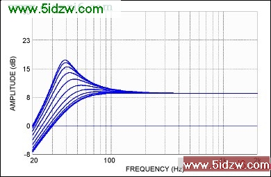
Figure 2. Simulation results of the dynamic bass boost from the subwoofer channel. The Q of the highpass filter is reduced while the cutoff frequency is also increased, as the subwoofer level approaches its limit.
The two op amps built into the MAX9736A are configured into a fourth-order lowpass subwoofer filter that complements the highpass filter used for the left/right channels.
J1 is the power-supply input connector chosen to be a standard laptop-type coaxial socket. A typical laptop power supply has an average output voltage of around 19V and serves as a good power source for the docking system. After some filtering through C1 and C2, the voltage is labelled PVDD and D1 is set to light blue when power is attached.
A simple reset circuit (through U6) is used to create a mute signal on power-up and power-down for both amplifier chips. This step avoids output transient noises due to input circuitry settling. The mute control threshold is programmed to approximately 10V with the R3 and R4 resistor-divider.
The MAX9736 features a patented filter-less modulation method which eliminates the need for bulky inductor-based filters. Only simple ferrite beads (L100 to L301) are required at the output.
A low f3 of 35Hz is targeted for the acoustic system, so a sixth-order alignment is used. That alignment includes a second-order highpass filter within the active crossover. The overall system is housed in a single box enclosure with the three loudspeakers, tuned port, and circuit PCB. The subwoofer is mounted as down-firing to minimize the box size and to help increase efficiency by compression loading. The resulting box volume is approximately 3.79l and the vented port is tuned to 54Hz. The outside overall box dimensions are approximately 355mm x 180mm x 120mm. The speaker crossover equalization is designed as a fourth-order Linkwitz-Riley at 250Hz; the speaker equalization for the satellites consists of a parametric EQ with f = 500Hz, gain = +6dB, Q = 0.5, and a shelving filter with f3 = 3.8kHz and a gain of +5.8dB. Figure 3 shows the system's response.
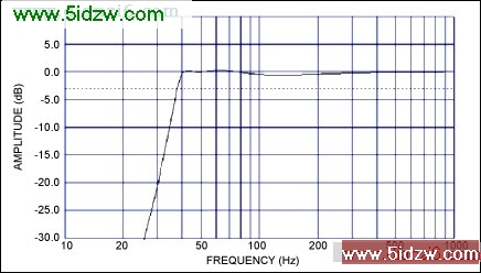
Figure 3. Total system simulated response shows maximally flat down to 40Hz.
The mechanical drawings included in this document are copies of those used to construct the prototype model. The prototype was built using 1/4in clear acrylic plastic and assembled with drilled/tapped screws and acrylic adhesive. A consumer product version might be constructed using a more cost-effective material such as wood, MDF, ABS, etc.
 ,Reference Design for a Class-D, 2.1 Channel, Audio Amplifier for an MP3 Player Docking Station
The resonant frequency, f0, can be calculated using the equation:
f0 = 1/(2 × π × √(L0 × C0))Where:
L0 = R108 × C107 × R107And the Q is:
C0 = C105
Q0 = √(L0/(C0 × R0²))A third EQ band is added that realizes a shelving filter and only needs an RC: one capacitor (C113 for boost; C114 for attenuation) and one resistor (R111).
As a stereo Class D IC, the MAX9736 also features two integrated op amps at the input. Available to use for general filtering, in this reference design those op amps are used to build a second-order highpass filter for the left/right channels. The op amps have their negative inputs and outputs accessible, so a multiple-feedback inverting filter configuration is used. C116/C216 are for blocking the DC-input voltage to reduce output offset.
Power Stage
The design features three channels of speaker power amplification. A MAX9736B is configured in stereo mode to drive the left and right speakers, and can provide 2 × 11W into 4Ω. For the third channel, a MAX9736A is configured as a mono subwoofer amplifier.In mono mode, the two Class D outputs of the MAX9736A are connected in parallel to allow for higher output power. In mono mode the subwoofer channel can deliver 30W into 4Ω (VDD = 19V). The input stage for the subwoofer channel is the same as that used for the left and right channels. After the input stage, the left and right signals are then summed using U5-B to create the mono subwoofer channel. R303 is used to set the subwoofer channel gain at the summing amp.
To enable a maximally flat response down to very low frequencies, the system is configured with a sixth-order filtered alignment for the subwoofer. This approach means that the fourth-order highpass response of the vented speaker is supplemented with a second-order electrical highpass in the active circuitry. U5-C is used to realize the noninverting Sallen-Key, second-order highpass filter for the subwoofer.
This system requires a high Q, which leads to 13dB of boost at 40Hz. To avoid overloading the speaker and amplifier, the Sallen-Key filter is set up to act as a sliding highpass; the filter acts dynamically as the amplifier output reaches its limit. The value of input resistor R305 is designed to reduce automatically (using the opto-coupled FET, U7) to a value so that the filter Q is lowered to 0.5, resulting in no boost at all.
The peak output voltage of the subwoofer amplifier, U2, controls the signal to the opto-FET. D6 and C16 form a peak detector, which senses the output peak level with a fast attack time. The operating threshold for the peak detector can be adjustable or fixed, depending on whether R7 is stuffed or R8/R9 are stuffed. The LED D5 turns on when this control circuit is active.
Figure 2. Simulation results of the dynamic bass boost from the subwoofer channel. The Q of the highpass filter is reduced while the cutoff frequency is also increased, as the subwoofer level approaches its limit.
The two op amps built into the MAX9736A are configured into a fourth-order lowpass subwoofer filter that complements the highpass filter used for the left/right channels.
J1 is the power-supply input connector chosen to be a standard laptop-type coaxial socket. A typical laptop power supply has an average output voltage of around 19V and serves as a good power source for the docking system. After some filtering through C1 and C2, the voltage is labelled PVDD and D1 is set to light blue when power is attached.
A simple reset circuit (through U6) is used to create a mute signal on power-up and power-down for both amplifier chips. This step avoids output transient noises due to input circuitry settling. The mute control threshold is programmed to approximately 10V with the R3 and R4 resistor-divider.
The MAX9736 features a patented filter-less modulation method which eliminates the need for bulky inductor-based filters. Only simple ferrite beads (L100 to L301) are required at the output.
Speakers and Physical Enclosure
The loudspeaker used for the subwoofer is a 5in-diameter model from Tymphany, part 830945, with a 4Ω nominal impedance and a resonance frequency of 47.4Hz. The 2in loudspeakers used for the left and right channels are model 830970, also from Tymphany. These loudspeakers have 4Ω nominal impedance and a resonance frequency of 147.5Hz.A low f3 of 35Hz is targeted for the acoustic system, so a sixth-order alignment is used. That alignment includes a second-order highpass filter within the active crossover. The overall system is housed in a single box enclosure with the three loudspeakers, tuned port, and circuit PCB. The subwoofer is mounted as down-firing to minimize the box size and to help increase efficiency by compression loading. The resulting box volume is approximately 3.79l and the vented port is tuned to 54Hz. The outside overall box dimensions are approximately 355mm x 180mm x 120mm. The speaker crossover equalization is designed as a fourth-order Linkwitz-Riley at 250Hz; the speaker equalization for the satellites consists of a parametric EQ with f = 500Hz, gain = +6dB, Q = 0.5, and a shelving filter with f3 = 3.8kHz and a gain of +5.8dB. Figure 3 shows the system's response.
Figure 3. Total system simulated response shows maximally flat down to 40Hz.
The mechanical drawings included in this document are copies of those used to construct the prototype model. The prototype was built using 1/4in clear acrylic plastic and assembled with drilled/tapped screws and acrylic adhesive. A consumer product version might be constructed using a more cost-effective material such as wood, MDF, ABS, etc.
Circuit Schematics
,Reference Design for a Class-D, 2.1 Channel, Audio Amplifier for an MP3 Player Docking Station