本应用指南讨论了各方面的电磁干扰( EMI ) 排放在开关模式电源( SMPS ) 。简短地概括了积极 条例在选定的区域和一个例子进行测量 百代唱片将得到。一些有影响力的相关因素的MOSFET的电磁干扰的开关电源 将实验研究。不同的操作模式的反激变换器 (硬开关和准谐振)将讨论有关其影响 电气噪声的产生。一般设计准则将得到。
1. Abstract
This application note discusses the aspects of ElectroMagnetic Interference (EMI)
emission in switch-mode power supplies (SMPS). A short overview of the active
regulations in selected regions and an example of the measurement of conducted
EMI will be given. Several MOSFET related factors influential on the EMI in SMPS
will be investigated experimentally. Different operating modes of a flyback converter
(hard switching and quasi resonant) will be discussed regarding their influence on the
字串9
electrical noise generation. General design guidelines will be given.
2. Basics of EMI
ElectroMagnetic Compatibility (EMC) is the ability of an electrical installation to work
properly in an electromagnetically polluted environment as well as not to disturb other
electrical devices due to the emission oft electromagnetic interferences. It means that
the electrical devices don’t influence themselves and one another, e.g. via the
common ground of control- and power circuits.
Electromagnetic interference is generated by a varying electric or magnetic field. It is
transmitted by means of conductive, inductive or capacitive coupling, through free
space or a combination of these means. It can be measured as conducted or
radiated interferences. This application note will focus mainly on conducted
interference.
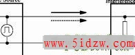
Conducted interferences can be distinguished into asymmetrical and symmetrical in-
PCB下载站
terferences, common and differential mode respectively. The differential mode cur-
rent only flows at the connecting line. The common mode circuit is closed across
parasitic capacitors C to the earth ground and the connecting lines. The interference
p
sink can be the main or another device connected with the source. Fig. 1 shows both
phenomena.
Fig. 1 Conducted interference mechanism
Periodical rectangle functions in time domain generate a discrete line spectrum de-
creasing with 20 dB per decade in the frequency domain. The spectral lines are mul-
tiples of the basic frequency (Fig. 2 a and c).
Real waveforms of power switch cycles with turn on (τ ) and turn off times (τ ) are
r f
trapezoidal.,大小:379 KB