标签:模拟电子技术基础,模拟电子电路,http://www.5idzw.com
Reference Voltage for Multiple,http://www.5idzw.com
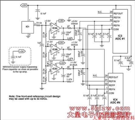
Figure 2. Also for ultrasound applications, a precision low-noise reference circuit drives up to 32 ADCs.
A DC level of +2.500V can be generated by a precision source (IC1), such as the MAX6066, followed by a 10Hz lowpass filter and precision voltage divider. The buffered outputs of this divider are set to +2.0V, +1.5V, and +1.0V, with an accuracy that depends on the tolerance of the divider resistors.
Those three voltages are buffered by the quad op amp IC2 (MAX4254), which is selected for its low noise and DC offset. The individual voltage followers are connected to 10Hz lowpass filters, which filter both the reference-voltage and buffer-amplifier noise to a level of 3nV/√Hz. The +2.0V and +1.0V reference voltages set the differential full-scale range of the associated ADCs at 2VP-P. The +2.0V and +1.0V buffers drive the ADCs' internal ladder resistances between them: 4kΩ divided by the number of ADCs in the circuit. As an example, 32 ADCs will draw 8mA from those supplies―a load current well within the capability of IC2 (MAX4252). The gain accuracy of this configuration can be almost arbitrarily good, depending on the accuracy grade of IC1 (here: MAX6066) and the tolerance of resistors in the voltage divider. The gain matching of each ADC in such a configuration is typically 0.1%. With the noise level below 3nV/√Hz at 100Hz, this circuit provides exemplary performance. As in Figure 1, the common power supply for all active components removes any concern regarding power supply sequencing when powering up or down.
With the outputs of the op amps matching better than 0.1%, these buffers and subsequent lowpass filters can be replicated to support as many as 32 ADCs. For applications that require more than 32 matched ADCs, a voltage reference and divider string common to all converters is highly recommended.