标签:模拟电子技术基础,模拟电子电路,http://www.5idzw.com
Level Shifting Digital Signals,http://www.5idzw.com
,Level Shifting Digital Signals
Level Shifting Digital Signals |
| By: Budge Ing |
| Abstract: With only a single-polarity power supply, digital systems often have a problem translating an opposite-polarity pulse train into a positive or negative pulse output. This application note presents three simple circuits that can level shift the digital signals easily and reliably. The MAX913 comparator is featured in the designs. This design idea appeared in the June 22, 2006 issue of Electronic Design magazine. For positive-supply systems, the circuit of Figure 1 transforms a negative pulse train into positive output pulses. The comparator shown () provides both in-phase and out-of-phase outputs. (If the system requires only one output phase, you can choose an alternative single-output comparator.) Voltage at the inverting input swings between 1.8V and 3.0V; R1 = R2 sets the noninverting input voltage to 2.5V. Outputs for the comparator shown then provide positive pulse trains. 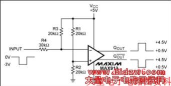 Figure 1. Operating on a positive supply, this circuit accepts negative input pulses and produces complementary bipolar outputs. For negative-supply systems, the circuit of Figure 2 transforms a positive pulse train into negative output pulses. Voltage at the inverting input swings between -1.8V and -3V; R1 = R2 sets the noninverting input voltage to -2.5V. The complementary comparator outputs provide negative pulse trains. 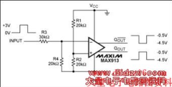 Figure 2. Operating on a negative supply, this circuit accepts positive input pulses and produces complementary bipolar outputs. Figures 3 and 4 use the comparator as a buffer, thereby providing an interface for systems in which the input signal and the system supply voltage have opposite polarities. The Figure 3 circuit enables a system with a positive supply voltage to accept negative pulses. In Figure 4, the input signal is positive and the system supply is negative. Both circuits use an NPN transistor to level shift the comparator's outputs by VBE (R5 + R4)/R5 ≈ 4.5V. (For single-phase outputs, you can choose an alternative single-output comparator.) 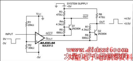 Figure 3. This circuit translates negative output to positive output pulses. It operates with a negative comparator supply and a positive system supply. 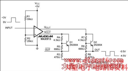 Figure 4. This circuit translates positive output to negative output pulses. It operates with a positive comparator supply and a negative system supply. |