Step 10. Set the ADC Input for TEMP+ to TEMP-
Set the polarity flipper back to normal by clearing the POL bit in the ADC register. Set the ADC positive input multiplexer for TEMP+ by setting MUXP[3:0] to 0x07 in the MUX register. Set the ADC negative multiplexer for TEMP- by setting MUXN[3:0] to 0x00 in the MUX register.
Step 11. Measure VBE2 using the ADC
The VBE2 voltage is measured from the TEMP+ to the TEMP- inputs to the ADC. The ADC is already configured and only needs to convert to get the resulting VBE2 voltage. To start the ADC conversion, set the STRT bit in the ADC register. The ADC will do a conversion and the result will be in the DATA register. Read the DATA register value and save as a 16-bit integer named VBE2 for later calculation.
Step 12. Set the ADC Input for VR2
Set the ADC positive input multiplexer for AGND by setting MUXP[3:0] to 0x09 in the MUX register. Set the ADC negative multiplexer for TEMP- by setting MUXN[3:0] to 0x00 in the MUX register (same as step 5). To measure the TEMP- input relative to AGND, the polarity flipper bit is used. Set the POL bit in the ADC register. The ADC is now setup with TEMP- as its positive input and AGND as its negative input.
Step 13. Measure VR2 using the ADC
To start the ADC conversion, set the STRT bit in the ADC register. The ADC will do a conversion and the result will be in the DATA register. Read the DATA register value and save as a 16-bit integer named VR2 for later calculation.
Step 14. Set the Current Source for I3 (64µA)
Set the current source for I3 by setting the IVAL[1:0] bits to 0x10 in the TEMP_CTRL register.
Step 15. Set the ADC Input for TEMP+ to TEMP-
Set the polarity flipper back to normal by clearing the POL bit in the ADC register. Set the ADC positive input multiplexer for TEMP+ by setting MUXP[3:0] to 0x07 in the MUX register. Set the ADC negative multiplexer for TEMP- by setting MUXN[3:0] to 0x00 in the MUX register.
Step 16. Measure VBE3 Using the ADC
The VBE3 voltage is measured from the TEMP+ to the TEMP- inputs to the ADC. The ADC is already configured and only needs to convert to get the resulting VBE3 voltage. To start the ADC conversion, set the STRT bit in the ADC register. The ADC will do a conversion and the result will be in the DATA register. Read the DATA register value and save as a 16-bit integer named VBE3 for later calculation.
Step 17. Set the ADC Input for VR3
Set the ADC positive input multiplexer for AGND by setting MUXP[3:0] to 0x09 in the MUX register. Set the ADC negative multiplexer for TEMP- by setting MUXN[3:0] to 0x00 in the MUX register (same as step 5). To measure the TEMP- input relative to AGND, the polarity flipper bit is used. Set the POL bit in the ADC register. The ADC is now setup with TEMP- as its positive input and AGND as its negative input.
Step 18. Measure VR3 Using the ADC
To start the ADC conversion, set the STRT bit in the ADC register. The ADC will do a conversion and the result will be in the DATA register. Read the DATA register value and save as a 16-bit integer named VR3 for later calculation.
Step 19. Set the Current Source for I4 (120µA)
Set the current source for I4 by setting the IVAL[1:0] bits to 0x11 in the TEMP_CTRL register.
Step 20. Set the ADC Input for TEMP+ to TEMP-
Set the polarity flipper back to normal by clearing the POL bit in the ADC register. Set the ADC positive input multiplexer for TEMP+ by setting MUXP[3:0] to 0x07 in the MUX register. Set the ADC negative multiplexer for TEMP- by setting MUXN[3:0] to 0x00 in the MUX register.
Step 21. Measure VBE4 Using the ADC
The VBE4 voltage is measured from the TEMP+ to the TEMP- inputs to the ADC. The ADC is already configured and only needs to convert to get the resulting VBE4 voltage. To start the ADC conversion, set the STRT bit in the ADC register. The ADC will do a conversion and the result will be in the DATA register. Read the DATA register value and save as a 16-bit integer named VBE4 for later calculation.
Step 22. Set the ADC Input for VR4
Set the ADC positive input multiplexer for AGND by setting MUXP[3:0] to 0x09 in the MUX register. Set the ADC negative multiplexer for TEMP- by setting MUXN[3:0] to 0x00 in the MUX register (same as step 5). To measure the TEMP- input relative to AGND, the polarity flipper bit is used. Set the POL bit in the ADC register. The ADC is now setup with TEMP- as its positive input and AGND as its negative input.
Step 23. Measure VR4 using the ADC
To start the ADC conversion, set the STRT bit in the ADC register. The ADC will do a conversion and the result will be in the DATA register. Read the DATA register value and save as a 16-bit integer named VR4 for later calculation.
Step 24. Calculate the Temperature
The temperature is calculated using the formula in Equation 1 above. The equation can be simplified by multiplying and dividing the constants in advance. The constant is applied to Equation 2 shown below.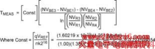
Equation 2. Simplified four-current temperature measurement equation.
Four-Current Method Example Using Real Data
The temperature was measured on an evaluation (EV) kit at room temperature using the procedure above with the following results.
For I1  4µA 4µA |
NVBE1 = 0x81AF | NVR1 = 0x0350 |
| For I2 60µA |
NVBE2 = 0x9048 | NVR2 = 0x32D4 |
| For I3 64µA |
NVBE3 = 0x90A5 | NVR3 = 0x3629 |
| For I4 120µA |
NVBE4 = 0x93E2 | NVR4 = 0x615c |