Well Grounded, Digital Is Analog
Abstract: An inexperienced designer may think that power decoupling capacitors and grounds are magic mystical things that absorb every bad noise. They are not. This application note discusses proper capacitor selection. It explains the failure of capacitors to decouple power buses above their self-resonance point. To illustrate the forces and characteristics of capacitors on a ground plane, an analogy to electrons is used. Electron behavior is comically illustrated. Guiding currents toward the ground star point in ground planes is demonstrated by slotting the plane.
Introduction
However surprising, some engineers really think that "ground" is a magic mystical thing that soaks up every bad thing like a black hole. We wish that were so. Designing a circuit would be far simpler.
Several years ago a customer had system noise issues. Looking at a printed circuit board with a seasoned analog design engineer, we found a lack of power decoupling capacitors. The ground plane had more holes than Swiss cheese. The analog engineer said: "I thought so. The digital guy struck again." The digital engineer in this case was brilliant, but he was just unlearned in analog techniques. The digital designer had failed to understand analog concepts like impedance, transmission lines, standing waves, power decoupling, and why grounds are divided in analog and digital areas. Now we do not want to "bash digital," and without digital we would miss out on many, many cool products. Unfortunately some engineering educators place so much emphasis on digital that analog skills are not well developed.
This application note discusses proper capacitor selection and how that decision affects a well-grounded design. Guiding currents toward the ground star point in ground planes is demonstrated by slotting the plane. The discussion begins by emphasizing why this is necessary and how digital and analog circuits share a sensitivity to noise.
Why Digital Is Analog
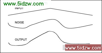
Figure 1. An input signal, noise, and the two added together.
Designers expect analog signals to be easily affected by noise. The lower waveform in Figure 1 is the direct result of adding noise to the signal, obviously a bad thing. However, digital is thought to be protected by thresholds. This thinking is erroneous, as we will see.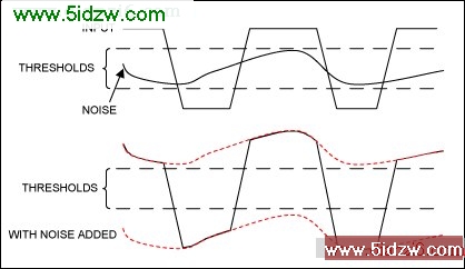
Figure 2. The top waveform is the input and noise. The bottom waveform has the noise added.
The thresholds in the digital portion of Figure 2 mean that the top waveform is really analog. How can this be? The region above the top threshold is the area where we call the signal a "one," and below the bottom threshold is the area that we call a "zero." What do we call the undermined area between the thresholds? That is analog. So the top waveform has noise present. Because the noise is below the threshold, digital thinking says that everything is OK. The bottom waveform does not cross a threshold, so it has to be OK!
It is time to see why this is digital mis-thinking.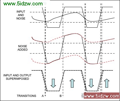
Figure 3, Signal plus noise with the resulting time errors.
Figure 3 repeats parts of Figures 1 and 2, but adds vertical lines to illustrate how the analog noise changed the output timing. Clearly, more than just missing the amplitude (up and down) thresholds is necessary. Looking carefully at the transitions, we see that the negative transition "A" is early compared to its intended position. The positive transition "B" is very close, so we drew a single line. Negative transition "C" is early and positive transition "D" is late. The noise has been transformed from amplitude error to time-jitter positional errors. If the signal is sampled at the arrows, the information will be preserved. However, if signal frequency was higher, the time error would be larger as a percentage, Eventually the sample points will be compromised.
These illustrations show why we say that digital is analog. That is, both analog and digital require care to preserve the signal purity. At this point we can consider the techniques that safeguard our wanted signals.
Selecting the Capacitor for the Application
One misconception is that capacitors take the bad noise of the power-supply lines and make it disappear into ground. Not true. Another notion is that capacitors are created equal. They are not. Poor capacitors do not help, and even high-quality capacitors are sensitive to frequency. All capacitors have unavoidable series resistance and inductance.
AVX® and Kemet® are capacitor companies that specify parasitic components and provide free Spice tools. The application notes on both sites are also very informative. These Spice tools allow us to graph the actual performance of the capacitors. For example, a 0.1µF capacitor is used as decoupling in many circuits. The impedance is frequency dependent, as Table 1 illustrates.
Table 1. Frequency vs. Impedance of a Typical 0.1µF Capacitor
Frequency (Hz)
Impedance (Ω)
1k
1.5k
33k
50
1.8M
1
10M
0.1
15.8M
0.023, self-resonance point
The Spice program allows us to evaluate and change several parameters to understand the circuit's function. The capacitor type can be ceramic or electrolytic. The size and working voltage are also variables.
In sensitive circuits we might see many decoupling components. Series inductors, resistors, and ferrite beads will form lowpass filters in conjunction with several capacitors. The capacitors are chosen to attenuate specific frequency ranges. It is not unusual to see four decoupling capacitors on a circuit. A large electrolytic serves as bulk current storage or low-frequency suppression; two ceramic capacitors are used to reduce interference in the 10MHz to 100MHz range. Finally, a small capacitor in the pico-Farad range is used to limit the higher radio frequencies.